- 您现在的位置:买卖IC网 > Sheet目录3860 > PIC18F67J10-I/PT (Microchip Technology)IC PIC MCU FLASH 64KX16 64TQFP
2009 Microchip Technology Inc.
DS39663F-page 27
PIC18F87J10 FAMILY
2.0
GUIDELINES FOR GETTING
STARTED WITH PIC18FJ
MICROCONTROLLERS
2.1
Basic Connection Requirements
Getting started with the PIC18F87J10 family of 8-bit
microcontrollers requires attention to a minimal set of
device pin connections before proceeding with
development.
The following pins must always be connected:
All VDD and VSS pins
All AVDD and AVSS pins, regardless of whether or
not the analog device features are used
MCLR pin
ENVREG (if implemented) and VCAP/VDDCORE pins
These pins must also be connected if they are being
used in the end application:
PGC/PGD pins used for In-Circuit Serial
Programming (ICSP) and debugging purposes
(see Section 2.5 “ICSP Pins”)
OSCI and OSCO pins when an external oscillator
source is used
Additionally, the following pins may be required:
VREF+/VREF- pins used when external voltage
reference for analog modules is implemented
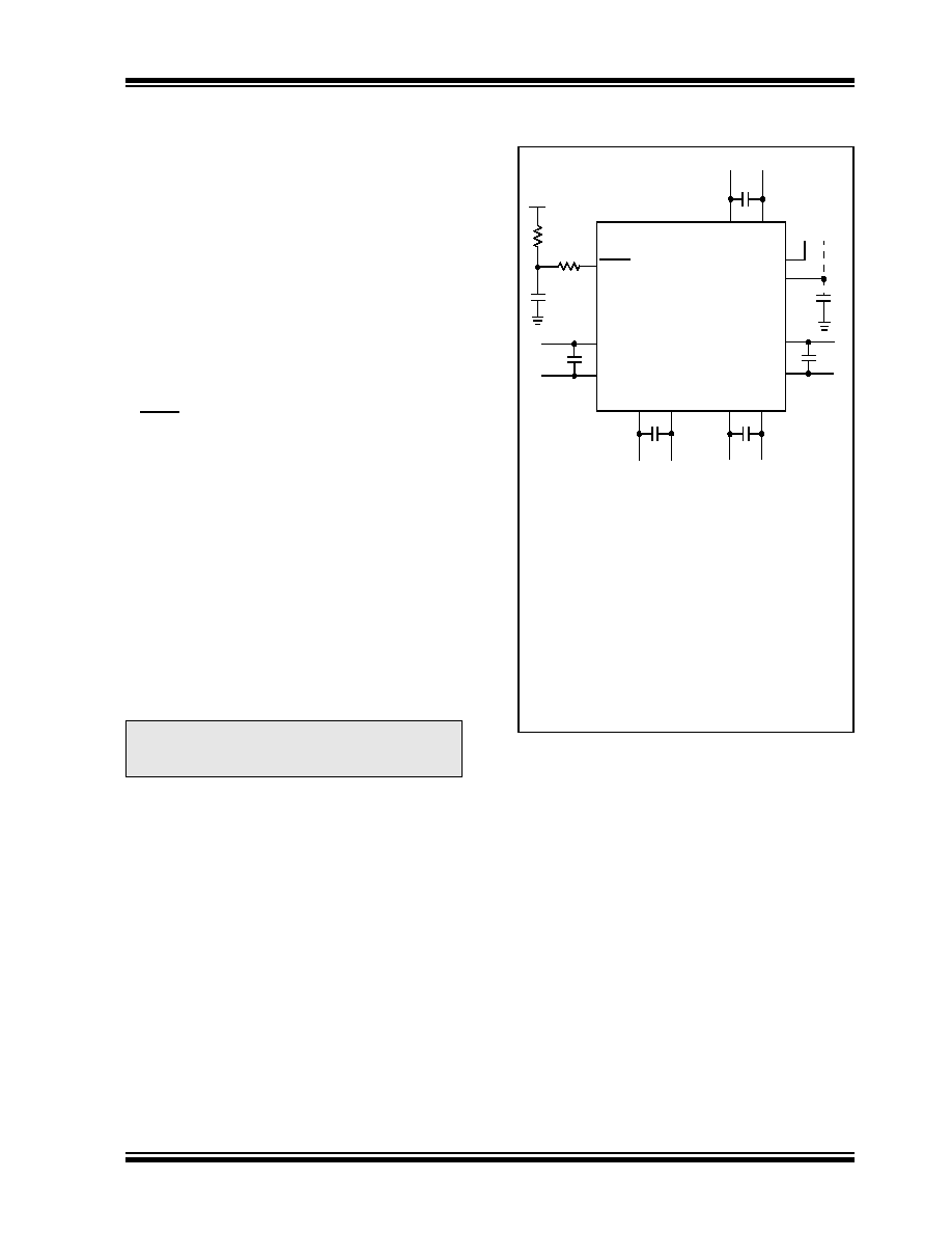
The minimum mandatory connections are shown in
FIGURE 2-1:
RECOMMENDED
MINIMUM CONNECTIONS
Note:
The AVDD and AVSS pins must always be
connected, regardless of whether any of
the analog modules are being used.
PIC18FXXJXX
V
DD
V
SS
VDD
VSS
VDD
AV
DD
AV
SS
V
DD
V
SS
C1
R1
VDD
MCLR
VCAP/VDDCORE
R2
ENVREG
(1)
C7
C2(2)
C3(2)
C4(2)
C5(2)
C6(2)
Key (all values are recommendations):
C1 through C6: 0.1
μF, 20V ceramic
C7: 10
μF, 6.3V or greater, tantalum or ceramic
R1: 10 k
R2: 100 to 470
Note 1:
explanation of ENVREG pin connections.
2:
The example shown is for a PIC18FJ device
with five VDD/VSS and AVDD/AVSS pairs.
Other devices may have more or less pairs;
adjust the number of decoupling capacitors
appropriately.
(1)
发布紧急采购,3分钟左右您将得到回复。
相关PDF资料
ATTINY12L-4PI
IC MCU 1K FLASH 4MHZ LV IT 8DIP
ATTINY12L-4PC
IC AVR MCU 1K FLASH 4MHZ LV 8DIP
DSPIC33FJ06GS102-I/MM
IC DSPIC MCU/DSP 6K 28-QFN
PIC18LF26J50-I/SO
IC PIC MCU FLASH 64K 2V 28-SOIC
ATTINY11-6SI
IC AVR MCU 1K FLASH 6MHZ IT SO8
PIC24FJ32GA004-E/ML
IC PIC MCU FLASH 32K 44-QFN
PIC32MX220F032D-I/TL
IC MCU 32BIT 32KB FLASH 44-VTLA
DSPIC30F2011-30I/P
IC DSPIC MCU/DSP 12K 18DIP
相关代理商/技术参数
PIC18F67J10T-I/PT
功能描述:8位微控制器 -MCU 128 KB FL 4 KB RAM RoHS:否 制造商:Silicon Labs 核心:8051 处理器系列:C8051F39x 数据总线宽度:8 bit 最大时钟频率:50 MHz 程序存储器大小:16 KB 数据 RAM 大小:1 KB 片上 ADC:Yes 工作电源电压:1.8 V to 3.6 V 工作温度范围:- 40 C to + 105 C 封装 / 箱体:QFN-20 安装风格:SMD/SMT
PIC18F67J11-I/PT
功能描述:8位微控制器 -MCU 128KB FL 3936b RAM 10 MIPS 51 I/O RoHS:否 制造商:Silicon Labs 核心:8051 处理器系列:C8051F39x 数据总线宽度:8 bit 最大时钟频率:50 MHz 程序存储器大小:16 KB 数据 RAM 大小:1 KB 片上 ADC:Yes 工作电源电压:1.8 V to 3.6 V 工作温度范围:- 40 C to + 105 C 封装 / 箱体:QFN-20 安装风格:SMD/SMT
PIC18F67J11T-I/PT
功能描述:8位微控制器 -MCU 128KB Flash 3936 bytesRAM 51I/O RoHS:否 制造商:Silicon Labs 核心:8051 处理器系列:C8051F39x 数据总线宽度:8 bit 最大时钟频率:50 MHz 程序存储器大小:16 KB 数据 RAM 大小:1 KB 片上 ADC:Yes 工作电源电压:1.8 V to 3.6 V 工作温度范围:- 40 C to + 105 C 封装 / 箱体:QFN-20 安装风格:SMD/SMT
PIC18F67J50-I/PT
功能描述:8位微控制器 -MCU 128KB FLH 3936Bs RAM USB 2.0 nanoWatt RoHS:否 制造商:Silicon Labs 核心:8051 处理器系列:C8051F39x 数据总线宽度:8 bit 最大时钟频率:50 MHz 程序存储器大小:16 KB 数据 RAM 大小:1 KB 片上 ADC:Yes 工作电源电压:1.8 V to 3.6 V 工作温度范围:- 40 C to + 105 C 封装 / 箱体:QFN-20 安装风格:SMD/SMT
PIC18F67J50T-I/PT
功能描述:8位微控制器 -MCU 128KB FLH 3936Bs RAM USB 2.0 nanoWatt RoHS:否 制造商:Silicon Labs 核心:8051 处理器系列:C8051F39x 数据总线宽度:8 bit 最大时钟频率:50 MHz 程序存储器大小:16 KB 数据 RAM 大小:1 KB 片上 ADC:Yes 工作电源电压:1.8 V to 3.6 V 工作温度范围:- 40 C to + 105 C 封装 / 箱体:QFN-20 安装风格:SMD/SMT
PIC18F67J60-I/PT
功能描述:8位微控制器 -MCU 128KB FL 12KB RAM 10BASE-T RoHS:否 制造商:Silicon Labs 核心:8051 处理器系列:C8051F39x 数据总线宽度:8 bit 最大时钟频率:50 MHz 程序存储器大小:16 KB 数据 RAM 大小:1 KB 片上 ADC:Yes 工作电源电压:1.8 V to 3.6 V 工作温度范围:- 40 C to + 105 C 封装 / 箱体:QFN-20 安装风格:SMD/SMT
PIC18F67J60T-I/PT
功能描述:8位微控制器 -MCU 128KB FL 12KB RAM 10BASE-T RoHS:否 制造商:Silicon Labs 核心:8051 处理器系列:C8051F39x 数据总线宽度:8 bit 最大时钟频率:50 MHz 程序存储器大小:16 KB 数据 RAM 大小:1 KB 片上 ADC:Yes 工作电源电压:1.8 V to 3.6 V 工作温度范围:- 40 C to + 105 C 封装 / 箱体:QFN-20 安装风格:SMD/SMT
PIC18F67J90-I/PT
功能描述:8位微控制器 -MCU Segmnt LCD 128KBFlsh 4KBRAM 12MIPS RoHS:否 制造商:Silicon Labs 核心:8051 处理器系列:C8051F39x 数据总线宽度:8 bit 最大时钟频率:50 MHz 程序存储器大小:16 KB 数据 RAM 大小:1 KB 片上 ADC:Yes 工作电源电压:1.8 V to 3.6 V 工作温度范围:- 40 C to + 105 C 封装 / 箱体:QFN-20 安装风格:SMD/SMT